


Component drawing

A component is a constituent part of a building (or other built asset) which is manufactured as an independent unit, subsystem or subassembly, that can be joined or blended with other elements to form a more complex item. Generally, components are ‘self-contained’ and sourced from a single supplier, typically the complete unit provided by that supplier rather than its constituent parts.
A combination of components may be described as an ‘assembly’.
Where a component is a bespoke item, it may be necessary to prepare a component drawing. Where a component is an off-the-shelf-product or a commonly-used element, a component drawing may already exist that can be re-used.
Component drawings might describe units such as; beams, windows, doors, sills, coping stones, and so on.
Component drawings provide detailed information about the individual units. They may be drawn at large scales such as; 1:10, 1:5, 1:2, 1:1, and so on. They may include information such as component dimensions, construction, tolerances, and so on. They may include references to the relevant parts of the specification providing information about materials and the minimum acceptable quality.
It is important that component drawings do not duplicate information included in separate specifications as this can become contradictory and may cause confusion.
Component drawing numbers may be prefixed by the letter C.
Component range drawings describe a range of components of a similar type. Where a range of components comprise a number of standard constructions, sub-component drawings may be prepared.
Assembly drawings represent items that consist of more than one component, showing how the components fit together.
[edit] Find out more
[edit] Related articles on Designing Buildings Wiki
- As-built drawings and record drawings
- Assembly drawing.
- CAD layer.
- Concept drawing.
- Design drawings.
- Detail drawing.
- Electrical drawing.
- Elevations.
- Engineering drawing.
- Exploded view.
- General arrangement drawing.
- Geometric form.
- Installation drawing.
- Orthogonal plan.
- Plumbing drawing.
- Projections.
- Scale drawing.
- Shop drawing.
- Section drawing.
- Technical drawing.
- Types of drawing.
- Working drawing.
Featured articles
Check out some of the best features and news from Designing Buildings as well as key stories from around the web.

Channel 4 broadcaster to host 125th anniversary ceremony.
Listed structures on the rail network
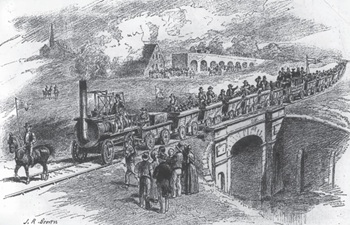
Heritage interests and operational requirements must be balanced.
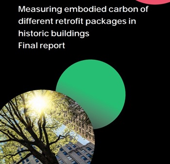
Historic England publishes research into embodied carbon when retrofitting traditional buildings.

New Prime Minister delivers on ECA call for cut in electricity costs.

CIOB reacts to the announcement of Andy Burnham as Prime Minister.

Heritage and conservation science workforce survey - Have your say.

England's Suburbs 1820-2020. Book review.

New, more proportionate and targeted approach for higher-risk building assessments.
Government brings British Steel into public ownership.

UKCW Birmingham returns with bold new theme and focus.
New guidance published on competence requirements for self-certification schemes.
Construction Management, 8 July

NEETs crisis drives interest in trades, but apprenticeships barriers remain.